
Automating an… enchanted rose?
Introduction
Info
This post was originally published in 2021, and has been adopted to this static-site from wordpress.
So- for Valentines day- since my wife is a huge fan of Disney cartoons, I got her a “Enchanted Rose”
It…. looks like this:
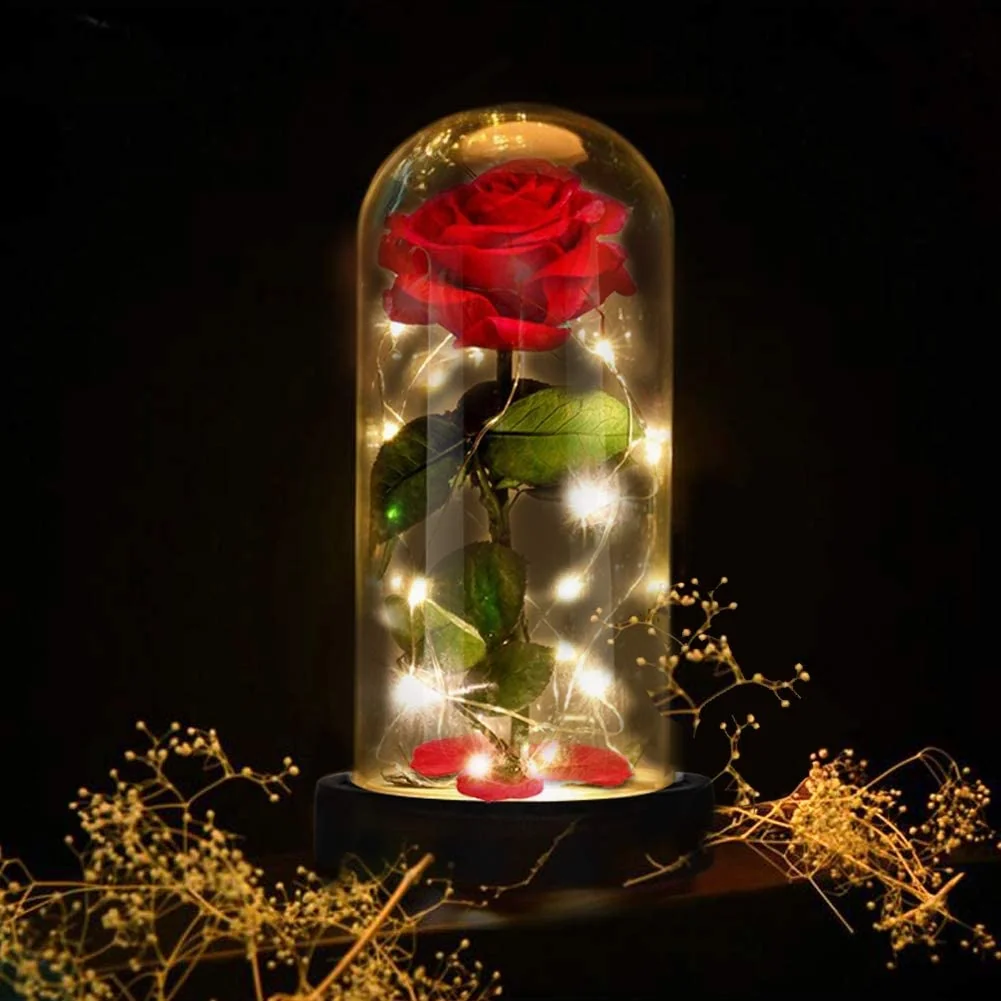
“Enchanted Rose”
You can find it here on Amazon: Enchanted RoseAmazon affiliate linkAs an Amazon Associate I earn from qualifying purchases at no additional cost to you; using this link helps support the site.
Well- overall, I guess it looks decent, and works as expected… However- it does not turn it self on at sunrise, or turn itself off when I go to sleep. This is unacceptable!
The goal of this article, is to fully automate this “Enchanted rose” using home assistant.
Do note- as far as I can tell- the LEDs contain an embedded chip, controlling their own lighting. If you desire to be able to customize the colors, or lightshow- you will need to replace the LED strips which came with this product. I cannot find a method to do this, without replacing the LEDs.
Parts and Tools Required.
- Enchanted RoseAmazon affiliate linkAs an Amazon Associate I earn from qualifying purchases at no additional cost to you; using this link helps support the site., or something similar.
- D1 MiniAmazon affiliate linkAs an Amazon Associate I earn from qualifying purchases at no additional cost to you; using this link helps support the site. (Or other ESP8266 variant.)
Below are tools/parts I assume you should already have…
- Soldering IronAmazon affiliate linkAs an Amazon Associate I earn from qualifying purchases at no additional cost to you; using this link helps support the site..
- SolderAmazon affiliate linkAs an Amazon Associate I earn from qualifying purchases at no additional cost to you; using this link helps support the site.
- A small phillips screwdriver…
- Helping HandsAmazon affiliate linkAs an Amazon Associate I earn from qualifying purchases at no additional cost to you; using this link helps support the site. - Not required, however- this makes many projects much easier. Also- these things are quite solid. I was very surprised at the build quality.
Getting Started
The first step, was to remove the bottom plate to expose the circuitry. I expected to find a small circuit for controlling the color LEDs. However, Instead, I only found a few diodes, and resistors.
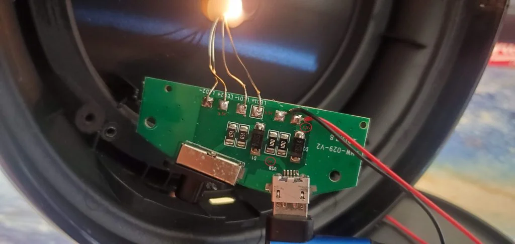
Circuit board, top view
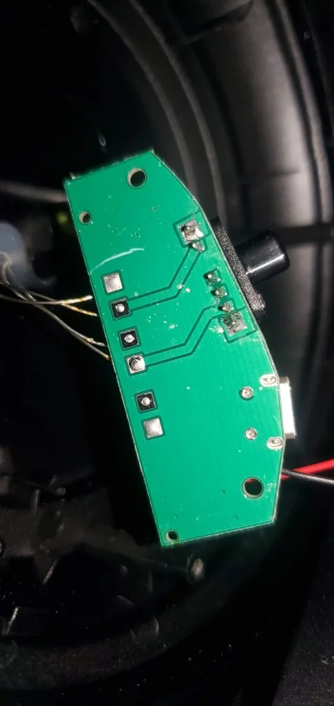
Circuit Board, bottom view
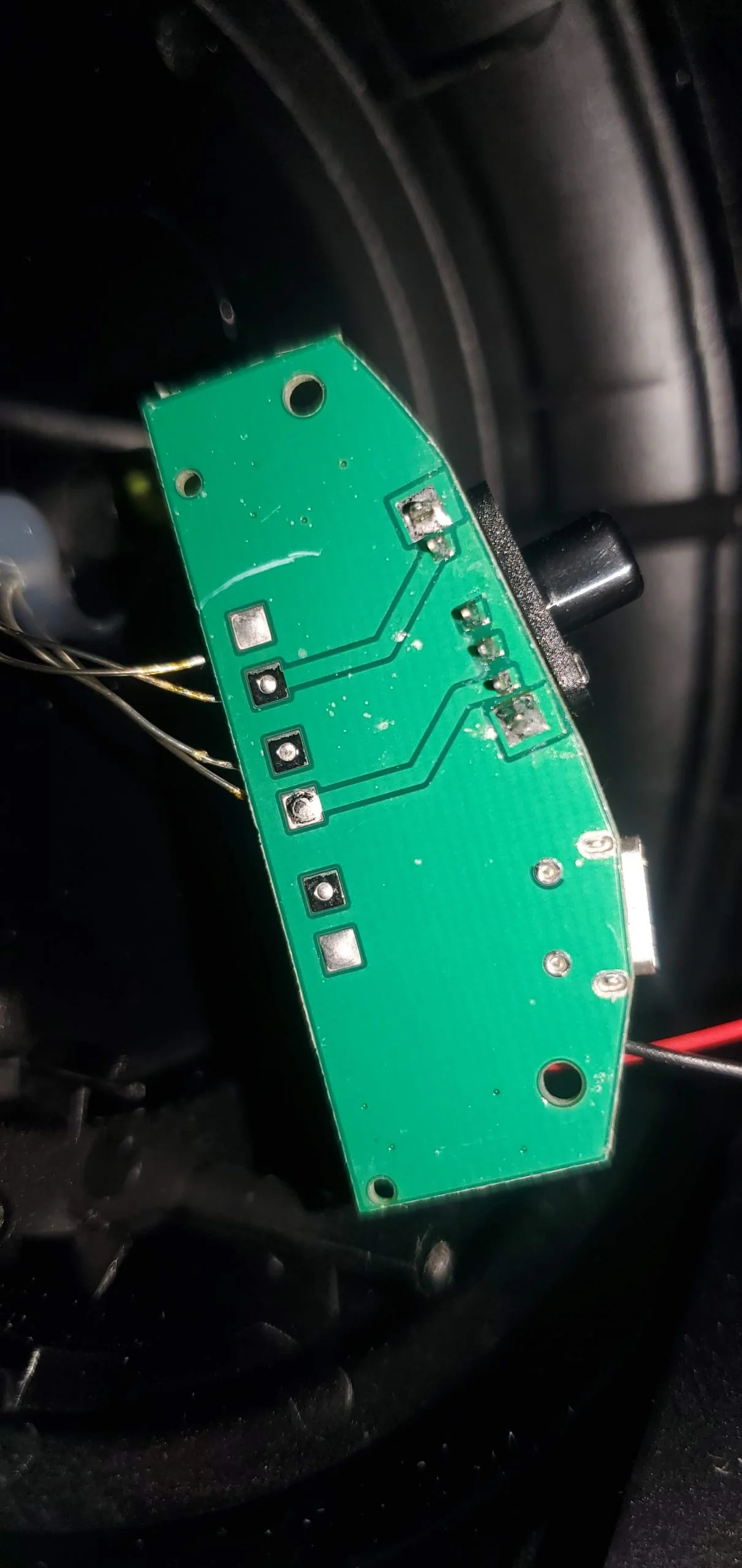
I am far from being an electrical engineer, so- don't quite me. However, the only purpose I can find in this circuit, is to reduce the incoming 5v, down to around 3v.
For anybody who actually does electrical work- Here is the data sheet for the diodes.
Having discovered this, I determined the best course of action, was to connect the d1 mini directly to the 5v power coming from the USB plug. I decided to remove support for batteries.
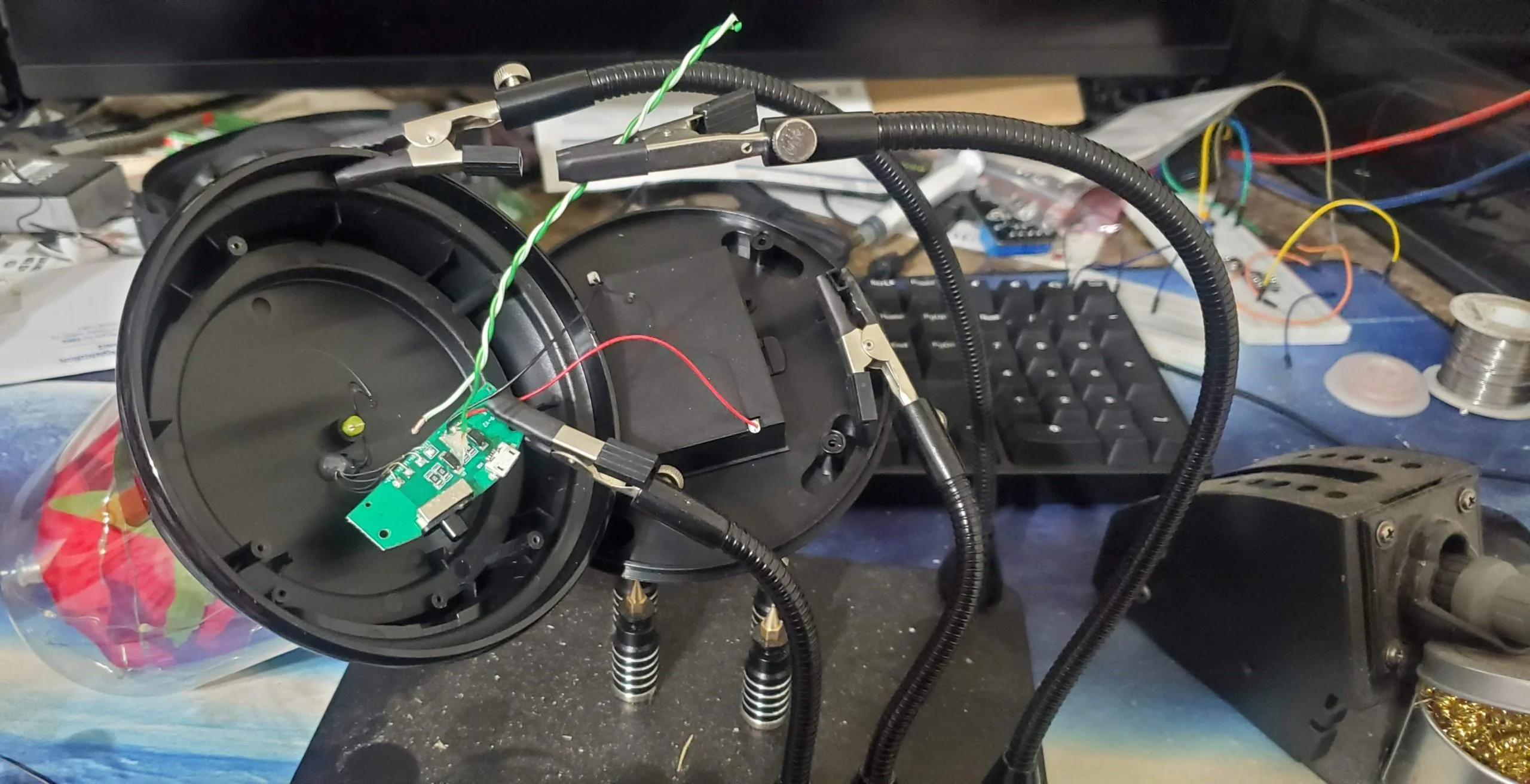
Using my "Helping HandsAmazon affiliate linkAs an Amazon Associate I earn from qualifying purchases at no additional cost to you; using this link helps support the site.".… I used some COPPER ethernet cable pairs to connect to power and ground on the circuit board. (Cheap ethernet cable is copper-coated aluminum, which does not solder worth a damn.) Any decent wire will work. I just had this laying around close.
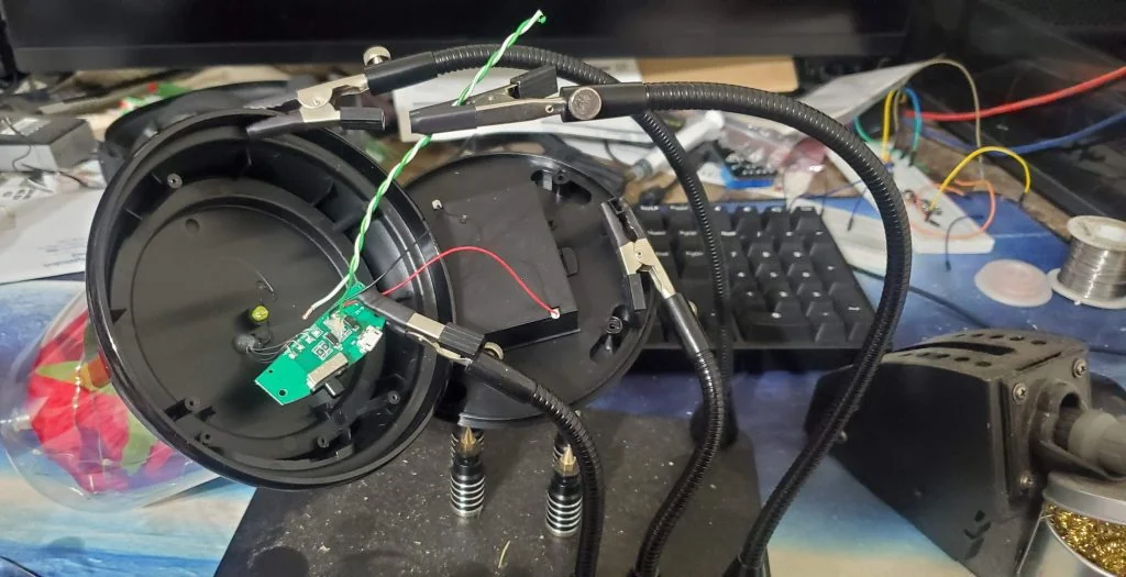
Soldering on wires to hot and ground on this circuit board using my helping hands.
After this was done, I used my die grinderAmazon affiliate linkAs an Amazon Associate I earn from qualifying purchases at no additional cost to you; using this link helps support the site. to cut out the battery compartment. Any sane person should probably stick to using a dremel tool, or something… BUT, I used a die grinder which is typically used for automotive and other metal working……
This is technically not required, as there is plenty of space to fit the d1 mini, without sacrificing the battery compartment. But- I had no intentions on using this with battery power.
The next step, was to solder in the d1 mini (or nodemcu… or other esp8266 variant.)
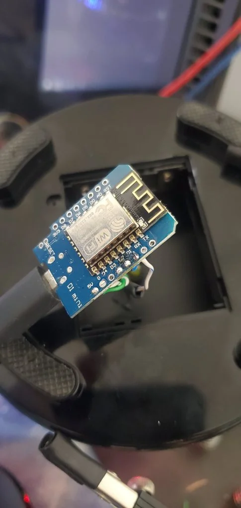
Wires soldered, and tested.
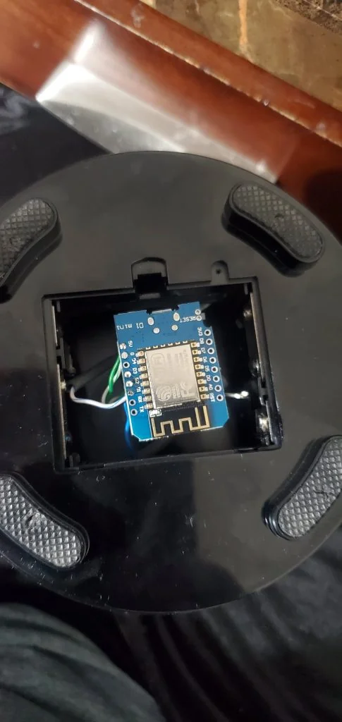
Testing final fitment.
For connections-
- 5v power is connected to the 5v pin. This power comes from the 5v+ from the circuit board.
- Ground is connected to the GND pin.
- One of the sets of lights connects to PIN D1, the other, to pin D2. (Don't use D3 or D4, they are reserved pins!) ESP8266 PIN Reference
After I tested locally, I reattached the bottom cover… and did my final testing.
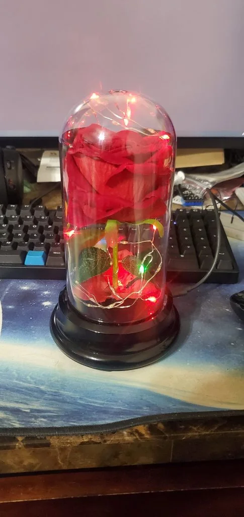
Color LEDs only
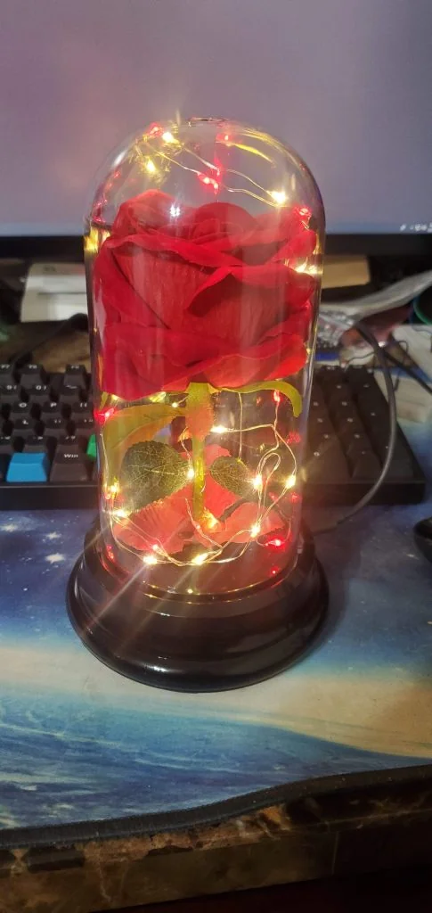
Color and White
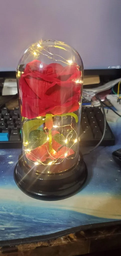
White Only
Images of the final product, working.
Within Home Assistant, the esphome device had already discovered itself. I just whipped up a very quick dashboard for testing.
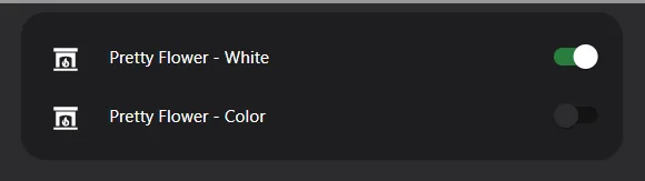
Simple, Stupid testing dashboard.
Finally- after having confirmed everything works as expected, I utilized the scheduling card and added schedules to turn it on and off. This can be installed via HACs.

Setting the schedule with the scheduler card.

But- ignore when we are on vacation.
After setting the schedule- everything else is handled automatically.

Lastly- here is my config for ESPHome.
Don't laugh at my device name. It works. I didn't know what else to refer to it as….
substitutions:
  devicename: "pretty_flower"
  friendly_name: "Pretty Flower"
  ip_address: 10.100.3.108
  gateway: 10.100.3.1
  <<: !include secrets.yaml

<<: !include config/common.yaml

esphome:
  name: ${devicename}
  platform: ESP8266
  board: nodemcuv2

switch:
  - platform: gpio
    pin: D2
    restore_mode: ALWAYS_OFF
    name: "${friendly_name} - White"
    icon: "mdi:string-lights"
  - platform: gpio
    pin: D1
    restore_mode: ALWAYS_OFF
    name: "${friendly_name} - Color"
    icon: "mdi:string-lights"

status_led:
  pin:
    number: GPIO0
    inverted: yes
Amazon Affiliate Links Used
This post DOES include Amazon affiliate links. If you found this content useful, please consider buying the products displayed using the provided links.
You will pay the same amount as normal, however, it does provide a small benefit to me. This benefit is usually used to purchase other products and hardware for which I can review / blog about.
I do not display advertisements on this site. As such, the only compensation from this service, comes from affiliate links. I do not ask for, or even accept donations.